Funkfernsteuerung— Wissen
Radio
US Army training video: How AM and FM Works
Radio, Wikipedia
A Practical Introduction to Radio Physics
A Practical Introduction to Radio Physics
Basic Amateur Radio, HF Propagation: The Basics
Electrical Basics
Units and what they mean
U = Spannung = Voltage => Volt / V
I = Strom = Current => Ampere / A
R = Widerstand = Resistance => Ohm / Ω
Ohm`s law
R = U ÷ I
U = R × I
I = U ÷ R
Example: calculating resistance if you know voltage and current (you want)
U = 5 V
I = 20 mA = 0.02 A
R = U ÷ I
R = 5V ÷ 0.02 A = 250 Ω
In words: So, if you know, you have a voltage source of 5 Volts (common for Arduino and similar circuits) and you want to have a current of 20 mA, you will achieve that by a resistor of 250 Ω.
Things are different with diodes (and LEDs)!
When you have a diode (LED=diode) in a simple series circuit, you have to modify the approach described above. This is because diodes have a forward voltage drop (i.e. they eat voltage), so you have to subtract that in your calculation.
Usource = 5 V
Udrop = 3.3 V (for a blue LED)
*I = 20 mA = 0.02 A
U = Usource - Udrop = 5 V - 3.3 V = 1.7 V
R = 1.7 V ÷ 0.02 A = 85 Ohm
LED calculator
LED calculator (simple)
LED calculator (also for combinations)
Common LED forward voltages
| Color | Voltage (Volts) |
|---|---|
| IR | 1.5 V |
| red | 2.0 V |
| orange | 2.0 V |
| yellow | 2.1 V |
| green | 2.2 V |
| true green | 3.3 V |
| blue | 3.3 V |
| white | 3.3 V |
| UV | 3.3 V |
| blue (430 nm) | 4.6 V |
Concise electronics for geeks
Check it out: Concise electronics for geeks
Arduino Resources
The official Arduino Tutorial and Guide are very helpful for learnimng the basic stuff:
Arduino – Official Guide
Arduino – Official Tutorial
Please watch those two short videos about how a program and Arduinos syntax works:
Sparkfun – Arduino Control Flow
Sparkfun – Arduino Programming Syntax
Actually, most of their short videos are pretty good (if you can handle full-on American Geek attitude…) to learn about general topics:
Sparkfun – Adventures in Science
Here is a collection of more Arduino resources:
EngBlaze – Arduino Resources 101 seems to be down at the moment
Some Arduino Syntax
Types
Variables and functions have types. They define what kind of data (mostly numbers) a variable can store and how big those can be.
Here are the most common:
| bool | Boolean Value (Truth) | true or false |
| int | Integers (whole numbers) | -32,768 to 32,767 |
| long | Long Integers | -2,147,483,648 to 2,147,483,647 |
| float | Floating Point (numbers with decimals) |
For more info, there is a section Data Types in the Arduino Reference
Comparison operators
To compare two values (for example in an if statement), there are the comparison operators.
| a < b | Is a smaller than b? |
| a > b | Is a greater than b? |
| a == b | Is a equal to b? |
| a != b | Is a not equal to b? |
| a >= b | Is a greater or equal to b? |
| a <= b | Is a smaller or equal to b? |
Comparison with tolerance
Sometimes, you want to compare the value from something like a potentiometer and let it do something if it is a certain value. The range is quite big however, so it makes sense to use a tolerance range for comparison. In this example we check if the potentiometer is roughly in the middle (a value of ca. 512). We check with a tolerance of +-100.
void setup() {
  pinMode(9, OUTPUT);
}

void loop() {
  int value = analogRead(A0);   // range 0-1023

  if (value > 512 - 100 && value < 512 + 100) {
  	digitalWrite(9, HIGH);  // LED on
  } else {
	digitalWrite(9, LOW);  // LED on
  }
}
Note that in the if statement, there are actually two comparisons value > 512 - 100 and value > 512 + 100. The first one checks if value is bigger than 412, the second one checks if value is smaller than 612. The && inbetween is a boolean AND. It simply means, it combines both comparisons and the whole statement is only true if both first AND second are true.
Boolean Operators
For a quick and good explanation of Boolean operator, please see Boolean.
| && | logical AND |
| || | logical OR |
| ! | logical NOT (true becomes false, false becomes true) |
Arduino Examples, Filters & Values
Example: Read from potentiometer and change LED brightness
This one is what we did in the last course. It reads the analog value of a potentiometer from pin A0 and changes the brightness of an LED connected to pin 9.
void setup() {
  pinMode(9, OUTPUT);

  Serial.begin(115200);
  Serial.println("Howdy!");
}

void loop() {
  int value = analogRead(A0);   // range 0-1023
  Serial.print("My analog value is: ");
  Serial.println(value);

  analogWrite(9, value / 4);   // divide to get a range from 0-255
}
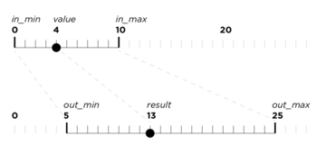
map()
map(val, in_min, in_max, out_min, out_max) transforms a value (val) from one range (in_min-in_max) to another range (out_min-out_max). This is very convenient.
Caveat: if val goes out of the input range (in_min-in_max), then the result can also be out of the output range.
constrain()
constrain(val, min, max) allows you to constrain (clamp) the range of a value (val) to a min and max value.
Example: Like before, but with a filter
Essentially this does the same thing as the example before, but filters the brightness value with a low-pass filter, so the LED behaviour will be smoother and slower. Try different numbers in the filter (like 0.99 and 0.01, or 0.8 and 0.2). It is important that those two numbers always add up to 1.0.
Please note that in this example we used the map function to map the range of analogRead (0-1023) to a range that makes sense for the analogWrite (0-255). Play around a little and get familiar with the map function. You could for example reverse the brightness behaviour
by writing map(value, 0, 1023, 255, 0) instead of map(value, 0, 1023, 0, 255).
There is a delay in the loop (20 ms), so the loop happens roughly 50 times per second (1000ms / 20ms). For filtering it is kind of important to have a fixed (and not too fast) speed of the loop.
float filteredBrightness = 0.0;   // this "memorizes" our filtered value

void setup() {
  pinMode(9, OUTPUT);

  Serial.begin(115200);
  Serial.println("Howdy!");
}

void loop() {
  int value = analogRead(A0);

  float brightness = map(value, 0, 1023, 0, 255);  // convert the range of the potentionmeter value
  brightness = constrain(brightness, 0, 255);  // clamp the result to a range of 0-255

  filteredBrightness = (0.95 * filteredBrightness) + (0.05 * brightness);
  Serial.print("Analog value: ");
  Serial.println(value);

  analogWrite(9, filteredBrightness);

  delay(20);   // wait a little, so our filtering can work
}
Example: Filtering a button press
This one reads the value of a button connected to pin 2. When the button is pressed (reads LOW), it sets the brightness to full (255), if it is not pressed, the brightness is set to 0. The brightness is again filtered with a low-pass filter, so the LED behaviour is smooth. The LED is connected to pin 9.
float filteredBrightness = 0.0;   // this "memorizes" our filtered value

void setup() {
  pinMode(9, OUTPUT);
}

void loop() {
  float brightness = 0;

  if (digitalRead(2) == LOW) {   // button is pressed
  	brightness = 255;
  }

  filteredBrightness = (0.95 * filteredBrightness) + (0.05 * brightness);
  analogWrite(9, filteredBrightness);

  delay(20);   // wait a little, so our filtering can work
}
Example: Capacitive Sensing
This is the thing we experimented with in the course. For it to work, you need to install the CapacitiveSensor library. In the menu go to Sketch > Include Library > Manage Libraries...
A quick introduction to the library is here: CapacitiveSensor. Read it :)
In our example, the send pin (see the introduction) is connected to pin 4 and the receive pin (connected directly to the piece of metal) is connected to pin 2.
Depending on your setup, it might be neccesary to see what range you actually get from the sensor (Variable total) and adjust the input range of the map function.
#include <CapacitiveSensor.h>

int LED = 10;
CapacitiveSensor sensor = CapacitiveSensor(4, 2);     // Receive pin is 2, Send pin is 4

float oldBrightness = 0.0;

void setup() {
  pinMode(LED, OUTPUT);
  Serial.begin(115200);
}

void loop() {
  long total = sensor.capacitiveSensor(30);
  Serial.print("total: ");
  Serial.println(total);

  float newBrightness = map(total,  25, 1400,  255, 0);
  newBrightness = constrain(newBrightness, 0, 255);

  oldBrightness = (0.9 * oldBrightness) + (0.1 * newBrightness);

  Serial.print("newBrightness: ");
  Serial.println(newBrightness);

  analogWrite(LED, oldBrightness);

  delay(20);   // slow down for filtering and serial
}
Arduino Examples, Light Dependent Resistors
Example: Reading a LDR
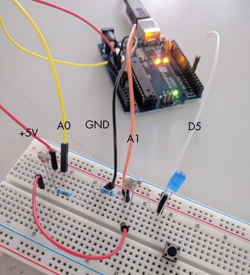
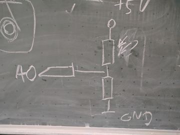
This example reads two LDRs (Light Dependent Resistors) and compares their value. LDRs are like normal resistors, but their resistance will become lower if they receive more light. The way to connect and read them with an Arduino analog input is to form a voltage divider with another (normal) resistor. The resistors used in this example are 10 kΩ. If the read values seem too big, try a smaller resistor.
In this example, if the value of A is more than 50 bigger than the value of B, the LED will light up. In order to make it work „in both ways“, so when you block light to either of the sensors, you can use if (abs(diff) > 50) instead of if (diff > 50).
Please check with the Serial Monitor first, if you receive meaningful values and have selected the right speed. Then use the Serial Plotter to see curves of the values.
void setup() {
  Serial.begin(115200);
  pinMode(5, OUTPUT);
}

void loop() {
  int valueA = analogRead(A0);
  int valueB = analogRead(A1);

  int diff = valueA - valueB;   // calculate the difference

  if (diff > 50) {   // if a is more than 50 bigger than b...
    digitalWrite(5, HIGH);
  } else {
    digitalWrite(5, LOW);
  }

  /* Print all the values and 0, 1204, so we trick autoscaling */
  Serial.print(valueA);
  Serial.print(",");
  Serial.print(valueB);
  Serial.print(",");
  Serial.print(diff);
  Serial.print(",");
  Serial.print(0);
  Serial.print(",");
  Serial.println(1024);

  delay(20);   // = 50 times/sec
}
abs()
abs(val) returns the absolute value of a value. E.g. 2 => 2, -2 => 2, 0 => 0
In German, this operation is called „Betrag“.